MQ" Command - Mode 1MQ" Command - Mode 2MV" CommandV" CommandThis document is written mostly in the style of a tutorial. There is a "Command Summary" near the end of it that attempts to be a sort of reference manual, but, for certain commands, all that you will find there is a link back into the body of the tutorial.
I have no idea how long it might take someone to learn how to use the editor effectively. When I began writing it, I was still editing the map databases using a text editor and my goal was to do the editing in an easier and more visual way. Over the years since then, it has accrued many different features, but it perhaps suffers a little from not having been designed as a whole. If you attempt to use this document to master the editor, please let me know how it goes.
  ncargcc -c PngAccess.c
  ncargcc -c TerminalInput.c
  ncargf77 -o EditEzmapData EditEzmapData.f PngAccess.o TerminalInput.o
Note: The above assumes that the "libpng" and "libz" support libraries are available. If NCAR Graphics has been installed in such a way that "ncargcc" and "ncargf77" don't know about them, you will have to modify the above commands appropriately (and you may have to install those libraries yourself).
Also, if you wish to access the RANGS/GSHHS database (which I highly recommend), you will have to download the appropriate files and edit the subroutine RNGSDI, in "EditEzmapData.f", to tell the editor the name of the directory in which you have put the files. For more information about downloading this database, look in the NCL documentation or go directly to the website of Rainer Feistel, who created it. In the interest of brevity, I will hereafter refer to this as just the "RANGS database", even though it builds on the work of Paul Wessel and Walter Smith, who created the GSHHS database and certainly deserve equal credit.
  Earth..4: our latest and greatest database ...

  Recent databases, all (unfortunately) using the same, somewhat erroneous, coast lines:

  Earth..1: the oldest EZMAPB database
  Earth..2: Earth..1 plus US counties, Mexican states, and Canadian provinces
  Earth..3: like Earth..2, but with US climate zones instead of counties

  Also available, but rather dated now:

  Earth..0-CO: EZMAPB version of the old 'CO' database, with area names added
  Earth..0-PO: EZMAPB version of the old 'PO' database, with area names added
  Earth..0-PS: EZMAPB version of the old 'PS' database, with area names added
  Earth..0-US: EZMAPB version of the old 'US' database, with area names added
Note: Throughout this tutorial, I use either "Earth..1" or "Earth..4" for my examples, so I recommend downloading at least those two. The former is the shortest and simplest of the modern databases, but the latter is a lot more interesting (and up-to-date).
Now, execute the editor binary by typing the command
EditEzmapDataThe editor first does a simple check to make sure that X11 is active and, if not, exits with an error message. If all goes well, it asks for the name of the ASCII file containing the database to be edited. Type the name, followed by
(RTRN).
Note: Throughout this document, I use the abbreviation (RTRN) to
refer to the typing of a RETURN.
The editor then asks you if you want to "merge contiguous edge segments".
Long boundary lines exist in the databases in segments of no more than 100
lat/lon points apiece. The editor is asking whether, as it reads the data,
it should merge segments that naturally fit together. There are certain
partially-edited databases for which one would answer "N", but at
this point it really won't make any difference, so answer "Y";
no (RTRN) is needed.
Note: Because the editor uses raw terminal input, you generally need a
(RTRN) only after entering a character string or a number. This
speeds things up a lot, but it can be a little startling when you first begin.
Another side effect is that, if you tell the editor to do something unwise
(which can happen at first), and you decide you want to kill it, the usual
Unix tricks that kill a program probably won't work (or, if they do, they'll
leave the terminal window unusable), so you'll probably have to kill the window
entirely and start over in a new one.
The editor should then read all the data from the specified file (reporting to you, as it does so, how many "areas", "edges", and "points" it finds), create an X11 "display" window with an initial view of the database, in cylindrical equidistant projection, and ask for your first command:
Enter command (H for Help, Q for Quit):You should resize the display window, arrange for both it and the original "command" window to be entirely visible, and make sure the command window is the active one before entering a command.
There is a viewport in the display window containing a sparsely-labeled grid, in yellow, overlaid with geopolitical outlines, in white. The center of the viewport is marked by a thick gray circle and two numbers, also in gray: the upper number is the latitude of the center point and the lower number is its longitude. There is a green label above the viewport, telling you the name of the database and the "level" at which you are viewing it (of which more later).
From this point on, you type commands in the command window and observe the effects of them in the display window.
Note: The editor is designed to hold all the data in memory at once, so you need a fairly fast and powerful workstation. I'm currently using either a 2.5 GHz MacBook Pro or a 3.06 GHz iMac; each has 4GB of memory; one has a 250GB, and the other a 500GB, hard drive. There is an upper limit on how much you can edit at once; the upper limits are set in PARAMETER statements in the code and are now pretty large, but still finite. It's also helpful to have a large display surface, particularly if you're georeferencing PNG files: my iMac has 1920x1200 pixels and I use every bit of that.
Q" ("Quit"); the editor asks if you really
want to quit and you have to answer "Y" if you do. As you might
guess, this feature was implemented after a few disastrous accidents.Note: You can generally type editor commands and simple "yes" or "no" responses in upper or lower case. Character strings representing names of files and areas, though, have to make correct use of upper and lower case.
H" ("Help"); you should get the following
response:
  Available commands are as follows:

    A => change info for picked Area
    B => change Background flag
    C => Check for errors and mark them
    D => change Dataset viewed
    E => Edit dataset in some way
    F => toggle Fill on/off
    G => toggle Grid on/off
    H => Help
    I => change Identifiers of picked edge
    L => change Level of area fill and editing
    M => Move center point
    N => write a frame to the NCGM
    O => Output edges to a named file
    P => Pick a point, an edge, and/or an area
    Q => Quit
    R => Read data (from background or from file)
    S => Show a particular area
    U => Update the display
    V => change miscellaneous Variables
    W => Write an updated copy of the dataset
    X => eXamine various dataset parameters
    Z => Zoom in/out toward/from center point

  The center point is gray.  The perimeter of the
  picked area is pink, the picked edge is red, and
  the picked point magenta.  A, E, and I commands
  make changes in the picked point and/or edge.

  Enter command (H for Help, Q for Quit):
Some of these commands (like "U") have an
immediate effect (like updating the display) and leave the editor expecting
another top-level command, but many of them cause the listing of a secondary
menu and leave the editor expecting a command from that menu. Some commands
involve even lower-level menus and some precipitate an interactive dialog.
Usually, from one of the lower-level menus, you can just type
(RTRN) to go back to the main menu without having changed
anything.The editor is pretty chatty about telling you what's going on (and you can't tell it to shut up - it doesn't have a non-verbose mode).
W" ("Write"),
which is used to write a new file containing the edited database. The editor
asks you a couple of questions: First, do you want to "include edges of type
0"? There will be edges of this type to worry about only if you imported data
(which are considered to be of type 0) but did not finish incorporating them
into the database; for the moment, just answer "N". (If you
answered "Y", it would then ask you if you wanted to write
only edges of type 0; frankly, I can't remember why I put that feature
in, but you would probably just answer "N".) It then writes a
file and tells you what name it used.When I did this just now, it used "Earth..1..1"; if I did it again, it would use "Earth..1..2", "Earth..1..3", ... "Earth..1.10", "Earth..1.11", and so on, through "Earth..1.99". (After that, it gives up and writes a file named "Earth..1.00" (overwriting any existing file having that name); you should never let the number of backup files get that big.)
W" command to write a copy of the database
in its current state. After a bit, I may have quite a few such files (for
example, "Earth..1..1", "Earth..1..2", ... "Earth..1.16").
  ncargf77 -o WriteLineFile WriteLineFile.f
  ncargf77 -o WriteNameFile WriteNameFile.f
When you execute "WriteLineFile", it asks you for the name of the edited ASCII database it is to process and then writes a binary file containing "line" information.
"WriteNameFile" is similar, but writes "name" information.
Executing each of these on the input file "Earth..1" creates "Earth..1.lines" and "Earth..1.names".
Now, you can use these files with NCAR Graphics. Here, for example, is the command necessary to compile a simple interactive program allowing you to take a quick look at an Ezmap database you've just edited:
ncargf77 -o EarthQuickLook EarthQuickLook.fWhen you execute "EarthQuickLook", it first asks for the name of an Ezmap map database and then for values of parameters telling it how to initialize Ezmap to produce the view that you want. Here's a sample dialog. I've set it up to produce a "gmeta", but you can easily modify it to produce a PDF file. There are two frames: a simple map and a color-filled one.
Some Additional (Optional) Steps
Once you have created the ".lines" and ".names" files, you can, if you wish,
create a ".areas" file by running a third program, which you create with the
following command:
ncargf77 -o WriteAreaFile WriteAreaFile.f
When you execute "WriteAreaFile", it asks you for the name of the edited ASCII
database it is to process and then appears to have gone into an infinite loop.
After a rather long time, it should finish writing a file that NCAR Graphics
uses only in a pathological situation (when a user has tried to display an area
so small that no boundary lines are visible).(I executed the command on my 3.06 GHz iMac and gave it the name "Earth..1"; it took a bit more than 15 minutes to create the file "Earth..1.areas". Then, I used "Earth..4" to create "Earth..4.areas" and it took about an hour and ten minutes. So, "WriteAreaFile" is a real time burner.)
See comments at the beginning of the Fortran source file for information about what it's writing.
You don't have to create the ".areas" file, but, if you do, you might also be interested in a couple of other programs.
The first program is created by the command
ncargf77 -o WriteAreaNcgm WriteAreaNcgm.f
and creates a "gmeta" containing plots that one can use to verify correctness
of the information in a ".areas" file. I won't bother to explain in detail
here what these plots mean; see the commenting in the Fortran source file for a
quick explanation. Suffice it to say that they are cell-array displays of the
globe, as represented by the information in the ".areas" file, at increasing
levels of detail.The second program is created by the command
ncargf77 -o WriteAreaSize WriteAreaSize.f
and is best executed using a command like
echo input_file_name | WriteAreaSize > output_file_name
(The "input_file_name" is something like "Earth..1", with no suffixed
".areas".)What you will find in the output file is a list of estimates of the sizes of the various areas defined by the input file, in square kilometers. These estimates are not particularly accurate (for one thing, they don't take into account that the earth is an oblate spheroid instead of a sphere), but, for the dataset "Earth..4", they aren't too far off from what you would find in a source like "Wikipedia". The areas are listed in the order defined by the database, but you can use your favorite editor or Unix tools to put them in a more sensible order and add commenting: here's an example for "Earth..4".
Another curious program is one created using the following command:
ncargf77 -o ExamineSquares ExamineSquares.f
When you execute "ExamineSquares", it asks for the name of an edited ASCII
database, reads it, and uses the information from it to create a "gmeta"
containing a number of plots showing, in finer and finer detail, how many
points of that database lie in each of a grid of squares covering the lat/lon
representation of the globe.
Z" ("Zoom") and
"M" ("Move").Z" ("Zoom"). It
prompts you to tell it whether you want to zoom in or out. Type an
"I" ("In") and observe what happens: what is now shown in the
viewport in the display window is centered at the same latitude and longitude,
but the part of the globe you see is half as wide and half as high as that in
the previous view. Type another "ZI" ("Zoom In") and you'll see
a change in the grid: In addition to yellow lines at 10-degree intervals, there
are now red lines at 1-degree intervals. As you continue to zoom in, grid
lines in other colors appear at 1/10th-degree intervals, 1/100th-degree
intervals, and 1/1000th-degree intervals. Try some "ZO" ("Zoom
Out") commands, as well.
Zooming one step at a time can become annoying, so there's a shortcut: if you
type a "Z" ("Zoom"), followed by a digit
between "1" and "9", and then an "I"
("In") or an "O" ("Out"), the view zooms in or out by the number
of steps specified by the digit you entered.
M" ("Move") and you are given a number
of choices: if you type an "L" ("Left"), an "R"
("Right"), a "D" ("Down"), or a "U" ("Up"), the view
moves in the chosen direction; the new center point is on the edge of the
previous view.
If you type an "M" followed by a single digit
between "0" and "9" and then one of "L",
"R", "D", or "U", the center of the
view is moved in the chosen direction (left, right, down, or up), by an
amount specified by the digit, but the size of the move is counterintuitive:
If "I" is the value of the digit, then the size of the move is
1/(2**I) times the half-width or half-height of the viewport: using
"0" moves the view all the way to the edge, using "1"
moves half-way to the edge, using "2" moves one-quarter of the way
to the edge, and so on. It may take a little while to get used to this, so you
should play with it for a bit.
Note that the size of a move, in degrees, depends on the zoom level. To position the center of the viewport more precisely, zoom in further.
M" ("Move") followed by a
"C" ("Coordinates") allows you to enter a desired latitude,
followed by (RTRN), and then a desired longitude, followed by
another (RTRN). In either case, if you just type
(RTRN) without typing the latitude or longitude, it continues
using the previous value.
Note: In general, when it's asking for a new value of a given variable, that's
how the editor behaves: if you just hit (RTRN), it uses the value
it was previously using for that variable. If you accidentally get into a
dialog involving the entering of several numbers, you can usually just hit
(RTRN) until it stops asking for more numbers, and you will have
changed nothing.
M" ("Move") followed by a
"V" ("Variables") allows you to change, not just the latitude and
longitude, but all three of the variables that determine what part of the globe
you're looking at and its magnification, as well as a couple of others that
have more to do with data entry and are described later. For more information,
look here.M"
command are for use while editing and will be described later. However, you
might, at this point, want to try an "M"
("Move"), followed by an A ("Area"), followed by an
"N" ("Name"), followed by the name (case matters) of an area that
you want to find (like "Maine" or "Egypt"), followed by (RTRN).
If it finds an area with the given name, it gives you information about that
area and then asks you if that's the area you want to move to. If you answer
"Y", it positions the view so that the chosen area just fits in
the viewport; if you answer "N", it tries to find another area
with the same name. For example, if you look for "Maine", it gives you the
following:
  Area found - definition is as follows:

    Index:              904

    Type:                 4
    Color:                4
    Parent:             985
    Full name: Land - North America - United States - Conterminous US - Maine
I will try to explain in detail, as I go along, what all this means and how
it is used; for the moment, suffice it to say that the state of Maine exists
in the database "Earth..1" with area identifier "904", it is a
type "4" entity (a state), it has a suggested color index of
"4", it is part of a "parent" entity with area identifier
"985", and its full name is "Land - North America - United
States - Conterminous US - Maine", each part of which is the name of an
entity contained in the entity whose name precedes it: "Land" is
the name for all land masses, "North America" is one of those land
masses, "United States" is a portion of
"North America", "Conterminous US" is a portion of
"United States" (the so-called "lower 48") and
"Maine" is a portion of that.G" ("Grid") command just toggles the grid
on and off (because
sometimes you need it and sometimes it's just in the way).
Similarly, the "F" ("Fill") command toggles
solid fill on and off.
As a side effect, if fill is on, the names of areas are written on the map.
(Try this while you're looking at "Maine" - use
"MANMaine(RTRN)",
as described above, to get there - and you see a flaw: Maine is labeled
all right, but the label for "Canada" is mispositioned; this is because it's
written at a lat/lon obtained by averaging the lats and lons of all the points
of its boundary that are visible in the current view, and that happens
to be somewhere over Maine.) Another feature of the color fill is that it is
only attempted when you're looking at a small enough area (as defined by a
user-settable parameter), so, as you zoom out, the fill spontaneously
turns off at some point.
The "N" ("NCGM") command writes the current
view to an NCGM called "gmeta" that is not finalized until one exits from the
editor, at which point it contains multiple frames, each the result of
issuing a particular "N" command. (I put this in so as to be
able to easily get snapshots of areas of interest.)
Similarly, an "O" ("Output") command is used to
write coordinate information for edges visible in the viewport (and clipped by
it) to an ASCII output file with a name of your choosing (which it asks you to
supply). Unlike the output from "N" commands, the output from
each "O" command is in a separate file by itself. I put this in
because, sometimes, people want excerpts of our data, for a given area, in a
human-readable (as well as machine-readable) format. Here's an example
(created from "Earth..4"), called India.out.
Note: If you want a graphical view of an outline file written by an
"O" command, you can use a program called "ExamineOutlineFile".
Download it using the link below and compile it using the command
ncargf77 -o ExamineOutlineFile ExamineOutlineFile.fWhen you execute "ExamineOutlineFile", it asks you for the name of the outline file it is to read and then writes a "gmeta" displaying its contents. You can modify the program to produce other types of graphical output; here's a PDF file produced from India.out (as mentioned above).
The "U" ("Update") command just redraws the
display. This was put in mostly because iconifying the display window and then
enlarging it again leaves it empty, but there are certain other times when it's
useful to be able to refresh the display.
The "D" ("Database") command is used to switch
to editing a different Ezmap database, but it isn't really all that useful
when you're actually editing. I put it in mostly for those times when I'm
using "N" commands to create more than one view of a particular
area in a "gmeta". I can, for example, fire up the editor on "Earth..1",
position it over a particular area (say, the "Conterminous US"), use an
"N" command to put a picture of that in "gmeta", use a
"D" command to switch to "Earth..2", and then use another
"N" command to put another picture in "gmeta", thus illustrating
the different versions of the area in the two databases.
The "V" ("Variables") command, like the
"MV" ("Move Variables") command, is used to
change the values of internal variables of the editor.
First, the editor tells you the current values of a group of variables. It
then prompts you to enter new values of those variables, one at a time. If you
just hit (RTRN) at a given prompt, the value is not changed. If
you enter a value that gives a Fortran error (like "TRQ" instead
of "541"), you are asked to re-enter the value. If you enter new
values for one or more of the variables, you see the effect when the display is
next redrawn.
A map database file is in ASCII and contains many lines of text, which are grouped into logical records. The logical records at the beginning of the file describe "edges" and the remainder describe "areas".
Note: Due to the way in which the design of the editor evolved over time, there are some inconsistencies in terminology with respect to the files derived from the database for direct use by Ezmap (mentioned above in the section Using an Edited Database File): What goes into a ".lines" file is "edge" information and what goes into a ".names" file is "area" information, while a ".areas" file contains a different sort of information about the areas defined by the database. By the time I realized that these inconsistencies had developed, it was too late to do anything about them without causing serious disruption (and, at that time, the editor was not a public tool).
  12   1   2  39 -74.00000 -74.67000-108.00000-109.50000
 -74.67000-108.50000 -74.50000-109.50000 -74.00000-109.50000 -74.00000-108.33000
 -74.33000-108.00000 -74.67000-108.50000
The "
12" on the first line says that the logical record contains
twelve real numbers defining the lat/lon coordinates of the points of the edge.
(So, in this case, there are six such points; in other logical records, this
number may be as large as 200, meaning that there are 100 such points.)
The "1" is the "type" of the edge: the value 1 says that it is
part of a land/water boundary; a 2 would say that it is part of a land-mass
boundary (e. g., between "Africa" and "Eurasia"); a 3, that it is part of a
national boundary (e. g., between "Iran" and "Iraq"); a 4, that it is part of a
state or provincial boundary (e. g., between "Colorado" and "Wyoming" or
between "Alberta" and "British Columbia"); and a 5, that it is a county-level
boundary (e. g., between "Cerro Gordo" and "Floyd" counties, in Iowa).
The "2" and the "39" are "area identifiers" for
the areas to the left and to the right of the edge, respectively (where "left"
and "right" are defined from the standpoint of an imaginary observer walking
along the edge in the direction in which it is defined). "Area identifiers"
are really indices into a list of named areas defined by the records at the
end of the file. In this case, "2" is the index of an area called
"Ocean" and "39" that of an area called "Bear Island".
The last four (real) numbers on the first line specify a bounding box for the edge: its largest and smallest latitude and its largest and smallest longitude, in that order.
The numbers in the remainder of the logical record specify lat/lon coordinates of the points of the edge. Each line defines four points except for the last, which may define fewer than four, but not less than one. No more than one hundred points may be defined in a single logical record.
The last edge record is followed by this exact line:
0 0 0 0 0.00000 0.00000 0.00000 0.00000Note: The first line of each "edge" record is read using the Fortran format "(4I4,4F10.5)" and the remaining lines are read using an "(8F10.5)".
   1 2 7  989 Antarctica
   2 2 1 1032 Ocean
   3 3 6  986 Russia
   4 3 6    3 Wrangel Island
   5 4 3   11 Adak Island
   .
   .
   .
1084 3 4   69 Maldives
1085 3 4  128 Arquipelago dos Bijagos
1086 4 2  985 District of Columbia
Each line is a single logical record containing descriptors for one of the areas defined by the edges in the file. The first number in each record is the "area identifier" for the area; in the "Earth..x" files, it increments by one from each record to the next, but in partially-edited files, this may not be the case. The second number is the "area type" (1 for "Land" or "Water", 2 for a specific body of land or water, 3 for a country, 4 for a state or province, and 5 for a county). The third number is between 1 and 8 and specifies a suggested color for the area. The fourth number is the index of the area's "parent". Following the fourth number is the name of the area.
The last line of the file looks exactly like this:
0 0 0 0Note: Each "area" record is read using the Fortran format "(I4,2I2,I5,1X,A64)".
The "type" of an edge may be thought of as a "level" - and, in fact, there is
an "L" ("Level") command that makes use of them
to allow you to view (and, to a limited extent, edit) a database at different
levels. If you view a database at level N, you are using edges having types
numerically less than or equal to N. (It isn't literally true, but you can
think of the database as having been constructed by first putting in all the
type 1 edges, then all the type 2 edges, and so on, through type 5, at each
step breaking previously-inserted edges into smaller pieces as necessary to
provide join points for the new ones.)
The edge types are as follows:
Areas need not be simply connected (or even connected) in the topological sense: for example, the area known as "Galapagos Islands" consists of a number of disconnected islands and the area known as "Africa" both includes a number of off-shore islands and has "holes" (lakes) in it.
The "type" of an area depends on its nature, as follows:
An area of type N may not have a parent of type greater than N: as you follow the chain of parent indices, you must encounter types of equal or lesser value. Equal values allow one to create group names: for example, the area named "Santa Catalina Island" is part of the area named "Channel Islands", which is the parent of several other islands and is part of the area named "California"; all of these areas are of type 4 (state level). Equal values also allow one to create alternate names, an example of which was given above: the area named "Xizang" is the parent of the one named "(Tibet)" and the area type of both is 4 (province level).
An edge of type N may only serve as part of the boundary of an area of type greater than or equal to N. The indices for the areas to its left and right must refer to the two areas in the hierarchy that have the edge as part of their boundaries and have the largest area types. For example, in "Earth..4", an edge along the boundary between the US and Canada has an edge type of 3, because it is part of a country boundary, but it has area indices for a US county (at level 5) on one side and a Canadian province (at level 4) on the other. The indices for areas above them in the hierarchy (the US and Canada, for example) may be found, when necessary, by following chains of parent indices.
There is more than one way to arrange areas in a hierarchy. What I have chosen
to do is, in many cases, a compromise. Consider, for example, the curious case
of Borneo, whose territory is shared by Brunei, Indonesia, and Malaysia: The
command "MANBorneo(RTRN)" ("Move Area Named
Borneo") offers you three possibilities, each of which is just a portion of
Borneo; there is no single area for the entire island of Borneo, such as there
is for the island of Java. Similar problems arise for the islands of New
Guinea and Timor. For some purposes, an S
("Show") command may be useful, since it works in a little different way.
CF ("Check Fill") command can be used at
each of the five different levels to help you find violations of this rule.Any area whose parent has the same area type (saying that it is at the same level in the area hierarchy) must also have the same color index.
The "EA" ("Edit Areas") command was intended
to make it easier to specify area colors (as well as other area descriptors),
but the increasing complexity of the databases has made it a bit problematical
to use.
Hierarchical Lists of Area Names
To see the complete hierarchical structure of "Earth..1", "Earth..2",
"Earth..3", and "Earth..4", follow links from the section of the Ezmap
programmer document called
"AREA IDENTIFIERS".
To create your own list of the hierarchical names of all the areas defined by a particular database (including one that you have edited), with an index, a type, a color index, and a parent index for each, you can download and compile the following two programs:
    ncargf77 -o WriteNameList WriteNameList.f
    ncargf77 -o WrapLines WrapLines.f
and then run a command like
WriteNameList < Earth..1 | sort | WrapLines > ! Earth..1.nmlst
to get a file like Earth..1.nmlst.The Unix command file WriteNameListFile can be used to make this slightly easier.
Here's another program that may be of (minute) interest:
ncargf77 -o WriteNcargNames WriteNcargNames.f
It's just like "WriteNameList", but instead of expecting you to pipe in the
ASCII form of the database, it asks you for the name of the database and then
calls the Ezmap routine "MDLNRI" to read
the required data from the ".lines" and ".names" files (so you can use it to
get name information from a database inside the NCAR Graphics installation).In general, unless you're inputting a file name or an area name, case doesn't matter: I show command characters in upper case, but they can be in lower case (and, in fact, I usually type them that way).
If you mistype one of the required characters, you can usually just use
(RTRN) to terminate the command without doing anything: the
editor's normal response to something it doesn't understand is to return to
the topmost menu without doing anything. Sometimes you have to use more than
one (RTRN).
Execute the editor. Tell it you want to edit "Earth..1" and that you do want to "merge contiguous edge segments". Type the command
MANGalapagos Islands(RTRN) ("Move to Area Named Galapagos Islands")
The editor responds with information about an area it knows about and asks
you if this is the area you want. Answer "Y". Five of the
Galapagos Islands, off the coast of Ecuador, should then appear in the display.
(There are actually more, but "Earth..1" only includes these five.)Suppose you decide that the little blip on the north end of the easternmost island looks wrong. (I have no good reason to suppose that this is true, but it makes a good example.)
To change it, the first thing you have to do is put that island somewhere near the center of the viewport. In this case, you can do that with one command:
MR ("Move Right")
The second thing you have to do is to "pick" the edge of the island.P" ("Pick")
commands. At the moment, nothing is picked, so issue a
"PP" ("Pick Point") command to pick the point
nearest the center of the display, the edge that contains it, and the area that
contains the center point when the command is issued:
PP ("Pick Point")
As a result of this command, the display window changes in various ways:
Left: 2 2 1 1032 Ocean" appears at
the left edge of the top of the display window, indicating that the
area to the left of the picked edge has area identifier "2",
is of area type "2" (a simple subdivision of "Land" or
"Water"), would be filled (if you turned fill on), with color number
"1", has, as its parent, area number "1032",
and is named "Ocean".
Right: 454 3 3 1039 Isla San Cristobal"
appear at the right edge of the top of the display window to say that
the area to the right of the picked edge has area identifier
"454", is of area type "3" (part of a
country), would be filled with color number "3", has, as
its parent, area number "1039", and is named "Isla
San Cristobal".
Picked area: 2 2 1 1032 Ocean" appear, in pink,
identifying the "picked" area; the various items in that legend have
meanings similar to those above.
PA" ("Pick
Area") command
PA454(RTRN) ("Pick Area 454")
Note that the pink label at the bottom changes and that the other islands are
no longer pink (because their boundaries are no longer part of the boundary of
the picked area). If you turned fill on (with an
"F" command), you'd see Isla San Cristobal in
pink and one of the other islands in green.E" ("Edit")
commands "ED" ("Edit Delete"),
"EI" ("Edit Insert"), and
"ER" ("Edit Replace").
You need a clear view of the picked items. With fill off (issue another
"F", if necessary), zoom in three steps:
Z3I ("Zoom 3 In")
At this point, you are zoomed in on the northern tip of Isla San Cristobal (the
point that I have chosen to consider erroneous). The point at the tip is in
magenta, indicating that it is the "picked" point. Each point of the edge is
labeled with its latitude (the upper number) and its longitude (the lower
number) and each segment of the edge is labelled with three numbers, telling
you (from "top" to "bottom", as viewed in an upright position) the area
identifier of the area to the left of the segment, the type of the edge, and
the area identifier of the area to the right of the segment. The zoom level
at which these labels appear is controlled by one of the internal variables
that you can change with a "V" ("Variables")
command.Actually, it may be that not all points and edge segments are labeled, even if the viewport range is smaller than the threshold value. If the points of an edge are too close together in the viewport, labels may be omitted in an attempt to keep them from overlapping labels previously drawn. This can be confusing: as you zoom in, new point labels may appear for points that you didn't realize were there.
Move the viewport down a little:
M2D ("Move 2 Down")
Suppose that the center point of the viewport is now approximately where you
would like the picked point to be; all you want to do is change the coordinates
of the picked point to the coordinates of the center of the viewport.ER" ("Edit Replace") command:
ER ("Edit Replace")
The "blip" at the north end of Isla San Cristobal has disappeared, because you
have moved the point that created it to a different position (the center of the
viewport).ED" ("Edit Delete") command:
ED ("Edit Delete")
The picked point is edited out of the picked edge and the picked point becomes
the one that preceded it on the edge. The center of the viewport is left at
the position of the deleted point so that, if desired, you can put it back
in.EI" ("Edit Insert") command:
EI ("Edit Insert")
A point having the lat/lon coordinates of the center of the viewport is inserted
following the picked point.MS" ("Move Start") command
MS ("Move Start")
to move the center of the viewport to the "start" of the picked edge and make
it the picked point.
The "ME" ("Move End") command
ME ("Move End")
moves to the "end" of the picked edge and makes it the picked point. If you
do either of these, you'll see that the point preceding the one you modified
is at the beginning of the closed loop.
End Point Oddities
If you delete the end point of the picked edge, using
  ME                                                                ("Move End")
  ED                                                             ("Edit Delete")
you can easily put it back in with an immediate
EI ("Edit Insert")
but if you delete the starting point of the picked edge, using
  MS                                                              ("Move Start")
  ED                                                             ("Edit Delete")
it's not so easy to put it back in, because I never provided a way to insert a
new point preceding the picked point. However, if the end points of the
edge have the same coordinates, there's a way to get around this, using a type
of "pick" that will be discussed a couple of sections further on:
  MS                                                              ("Move Start")
  PE                                                                ("Pick End")
  EI                                                             ("Edit Insert")
which moves the center of the viewport to the starting point of the closed
loop, making it the picked point, but then moves the picked point to the end
of the edge (without moving the center of the viewport), and then does the
insert. (Note that this doesn't quite restore the original definition of the
closed loop: it now starts and ends at a different point.)
Note: There is a rather complicated general way to restore the deleted
first point of any edge: see the "Command Summary" entry for
ED.)
The "MF" ("Move Forward") command
MF ("Move Forward")
moves the center of the viewport to the point following the picked point on
the picked edge and makes it the picked point.
The "MB" ("Move Backward") command
MB ("Move Backward")
moves the center of the viewport to the point preceding the picked point on
the picked edge and makes it the picked point.Here's a case in which these commands appear not to have worked properly: If the end points of the edge have the same coordinates and the picked point is at the beginning of the edge and you move backward or the picked point is at the end of the edge and you move forward, then the picked point becomes the one at the other end of the edge, but it looks as if nothing happened, because the first and last points are at the same position. You sort of have to keep a mental picture of the edge to understand what's going on.
Other cases in which a "Move Forward" or "Move Backward" seem not to be working occur when importing digitized data (which I will describe later). Such data frequently have repeated points in them; the editor doesn't tell you about such repeated points; they make their presence known by their effect on "Move" commands. An even worse case is when the first and last points of a closed loop appear to be in the same position, because their lat/lon coordinates match to within machine epsilon, but they are actually slightly different; this can cause problems both for the editor's "Check" command (which looks for certain kinds of errors) and for Ezmap itself (in the form of "fill leakage").
PF" ("Pick Forward"),
"PB" ("Pick Backward"),
"PS" ("Pick Start"), and
"PE" ("Pick End"):
  PF                                                            ("Pick Forward")
  PB                                                           ("Pick Backward")
  PS                                                              ("Pick Start")
  PE                                                                ("Pick End")
are used to pick a different point on the current picked edge without moving
the center of the viewport to that point.
The command "PN" ("Pick Nearest"):
PN ("Pick Nearest")
is just like "PP" ("Pick Point") in that it
picks the point nearest the center point of the viewport, but it doesn't move
the viewport.
The command
"PO" ("Pick Off")
PO ("Pick Off")
returns the editor to its default state, with nothing picked.
  MnF                                                         ("Move n Forward")
  MnB                                                        ("Move n Backward")
  PnF                                                         ("Pick n Forward")
  PnB                                                        ("Pick n Backward")
where "n" is a single digit from 1 through 9, are just like the commands
without the inserted "n", but refer to a point "n" steps away along the picked
edge. If that many steps would carry you past the first or last point of the
edge, you'll end up at the other end of the edge, but not beyond. (For example,
if you're three steps away from the end of the edge, both "M4F"
and "M9F" move you to the beginning of the edge.)EE" ("Edit Edge") command
EE(RTRN) ("Edit Edge")
You'll see five possibilities, but the basic ones are "B",
"C", and "D", which stand for "Break", "Create", and
"Delete", respectively.EEC" ("Edit Edge Create") command:
EEC ("Edit Edge Create")
causes a new edge to be created, containing one point, at the position of the
center point of the viewport. Try moving the viewport somewhere and doing the
following:
  EEC                                                       ("Edit Edge Create")
  M3R                                                           ("Move 3 Right")
  EI                                                             ("Edit Insert")
  M3U                                                              ("Move 3 Up")
  EI                                                             ("Edit Insert")
  M3L                                                            ("Move 3 Left")
  EI                                                             ("Edit Insert")
  M3D                                                            ("Move 3 Down")
  EI                                                             ("Edit Insert")
You have created a little rectangular closed edge - a box - in the database.EEB" ("Edit Edge Break") command:
  MS                                                              ("Move Start")
  M2F                                                         ("Move 2 Forward")
  EEB                                                        ("Edit Edge Break")
The picked edge is broken into two edges at the picked point; the first of
these is the picked edge.EED" ("Edit Edge Delete") command:
EED ("Edit Edge Delete")
You are asked if you really want to delete the edge and must answer
"Y"; anything else leaves the edge in the database.Note: Be very careful in deleting edges, as there is no easy way to get a deleted edge back.
Observe that the remaining portion of the box is no longer picked and that it has turned green. This is because it is a newly-created edge with a line type of zero. Later, we'll see how to change that.
Get rid of the rest of the box you created with the commands
  PP                                                              ("Pick Point")
  EED                                                       ("Edit Edge Delete")
Obviously, there's a limit to how much editing of this sort one wants to
do, because it's tedious and slow.
MQ ("Move Quick") commands to trace the
desired geopolitical outlines on that background, in effect "reading" them
from the PNG.
Note that ASCII output files produced by "O" ("Output") commands
can be put through a relatively simple filter to produce ASCII input files.
There are some extra lines in the output files, but the formats of the lines
they have in common are the same.
RF" ("Read File") command:
RF ("Read File")
The editor prompts you for the name of the file to be read. I will describe
the format of the file by example. Here's one called
New.Providence, containing outline data for an
island in the Bahamas (called, oddly enough, "New Providence") that is more
nearly correct than that used in the database "Earth..1". It also contains
outline data for three nearby islands that aren't even in "Earth..1". In the
interest of brevity, I have somewhat abbreviated what follows and annotated the
lines; follow the link above to see the actual file.
Ocean                      <--  name of area on left                  +
New Providence Island      <--  name of area on right                 |
  -77.499542   25.000000   <--  lon/lat coordinates of 1st point      |
  -77.522171   25.001221   <--  lon/lat coordinates of 2nd point      | (edge 1)
   ...   ...   ...   ...   ...                                        |
  -77.499542   25.000000   <--  lon/lat coordinates of last point     |
                           <--  end of edge                           +
Paradise Island            <--  name of area on left                  +
Ocean                      <--  name of area on right                 |
  -77.353783   25.086670   <--  lon/lat coordinates of 1st point      |
  -77.347557   25.084610   <--  lon/lat coordinates of 2nd point      | (edge 2)
   ...   ...   ...   ...   ...                                        |
  -77.353783   25.086670   <--  lon/lat coordinates of last point     |
                           <--  end of edge                           +
Unnamed Island             <--  name of area on left                  +
Ocean                      <--  name of area on right                 |
  -77.302109   25.096640   <--  lon/lat coordinates of 1st point      |
  -77.295502   25.097080   <--  lon/lat coordinates of 2nd point      | (edge 3)
   ...   ...   ...   ...   ...                                        |
  -77.302109   25.096640   <--  lon/lat coordinates of last point     |
                           <--  end of edge                           +
                           <--  name of area on left (omitted)        +
Ocean                      <--  name of area on right                 |
  -77.245453   25.089140   <--  lon/lat coordinates of 1st point      |
  -77.237663   25.085421   <--  lon/lat coordinates of 2nd point      | (edge 4)
   ...   ...   ...   ...   ...                                        |
  -77.245453   25.089140   <--  lon/lat coordinates of last point     |
                           <--  end of edge (and end of file)         +
Each "edge" defined by the file consists of a line containing a name for the
area to the left of the edge, a line containing a name for the area to the
right of the edge, a series of lines in Fortran format "(2F12.6)" defining the
coordinates of the points of the edge (which can be either in lat/lon order or
in lon/lat order, but have to be in the same order for the whole file), and a
blank line. The names must begin in column 1 and must not be more than 64
characters long. Each of the lines containing a name may be blank, if the name
of the area is unknown: however, the blank lines must still be present.Execute the editor, tell it you want to edit "Earth..1", and that you want to "merge contiguous edge segments". Then, execute the command
MANNew Providence(RTRN) ("Move to Area Named New Providence")
and answer "Y" to the first (and only) choice offered.Pick the edge defining the area (as well as the area itself and a point on the edge) using the command
PN ("Pick Nearest")
The edge you want to replace is now highlighted in red. Yellow arrows tell you
where it begins and ends. Note that the edge is closed and that it is traced
in a counterclockwise direction. There are red labels telling you the lat/lon
positions of all the points of the edge (except for the picked point, which is
magenta). The labels at the top of the display window give you information
about the picked edge.Use the command
RFNew.Providence(RTRN) ("Read File "New.Providence")
to read the file containing the new data. When it asks you if the coordinates
are in an order other than the expected one, answer "Y". (When
the coordinates are in the expected order, you can just use
(RTRN).Some faint green lines have appeared, along with another bunch of point labels, in white. Unpicked edges of type 0 (which all imported edges are) are shown in green, rather than in white. Sometimes, the grid and the point labels are essential, but, in this case, they're just in the way. Let's make it easier to see the edges we're dealing with. First, turn the grid off:
G ("Grid")
Then, reset the variable that controls point labelling:
V.01(RTRN)(RTRN)(RTRN)(RTRN)(RTRN)(RTRN) ("Variables")
Point labels will now appear only when the range of the view is less than .01
degrees. The first (RTRN) is necessary to signal the end of the
constant ".01"; the others just say to leave the other five variables unchanged.
(Fortunately, you shouldn't have to use "V" commands very often.)
Now, you can see the imported green edges clearly. You want to delete the old edge and copy its edge type ("1") and its area identifiers ("583" and "2") to the new, more precise, green edge that is replacing it. (At this point, I usually jot these numbers down on a notepad, but your memory may be better than mine.)
Deleting the old edge is easy (but remember that there's no easy way to get it back, so be sure you're deleting the right one):
EED ("Edit Edge Delete")
You'll then have to type a "Y". Again, think about it!Note: I usually delete old edges at the last possible moment, in case I forgot to write down all the information I needed from them. I have done things in a different order here so as to keep the example simpler. Doing it the way I usually do it may require a number of "Move" and "Pick" commands.
Now you can pick the green line:
PN ("Pick Nearest")
The new edge is now the picked one. It is highlighted in red and the red
labels at the top display information for it. Yellow arrows tell you where it
begins and ends. Note that it is closed and that, unlike the original edge,
it is traced in a clockwise direction (so its left and right area identifiers
are "2" and "583", instead of "583" and "2"). You have to change its type
and its right area identifier. (Its left area identifier is already what you
want, because the imported name "Ocean" was found in "Earth..1" and the editor
tried to be helpful, but its right area identifier points to a new area, with
index "1087", area type "1", color index "8", and parent index "0", that was
created for you; the "1", the "8", and the "0" are default values.)
Change the descriptors of the new line with an I
("Identifiers") command (type it slowly and watch the prompts to see what's
happening):
I1(RTRN)(RTRN)583(RTRN) ("Identifiers")
The principal task is complete: You have replaced the old edge defining "New
Providence" with a more precise one and transferred the appropriate area
identifier information to it. (The picked area, as indicated by the pink
legend at the bottom of the display window, is one called "New Providence
Island", which you don't really want, but you can deal with it later.)Now you should incorporate "Paradise Island", which was the second edge defined by the imported file. The easy way to get to it is with the command
MANParadise Island(RTRN) ("Move to Area Named Paradise Island")
Again, you have to give it a "Y" to complete the move. Then,
use another
PN ("Pick Nearest")
to pick the imported edge. Examine the picked-edge information at the top of
the display window: you need to change the type of the edge to a "1", but you
can leave both the left and right area identifiers alone:
I1(RTRN)(RTRN)(RTRN) ("Identifiers")
The new area on the left of the edge, called "Paradise Island", was created for
you during the import, but with default values for its type, suggested color,
and parent index. What values should you use for them? In this case, since
you are dealing with an island in the Bahamas, the appropriate thing is for it
to have the same values for these quantities as "New Providence" had. What
were those values? Remembering that "New Providence" was area number 583, you
can use the command
PA583(RTRN) ("Pick Area 583")
and examine the pink label at the bottom of the display window. It tells you
that the type of that area was "3", its color was "3", and its parent was
"1031". Make a note of these and then go back to "Paradise Island" (area
number 1088 - this is why I make notes ... :-):
PA1088(RTRN) ("Pick Area 1088")
To change all the information for this area, issue an
"A ("Area") command incorporating the
information from area 583:
A3(RTRN)3(RTRN)1031(RTRN)(RTRN) ("Area")
The final (RTRN) is in response to a prompt allowing you to
specify a new name for the area, which you don't want to do, because the name
from the imported data file is actually the one you want.Now, deal with the third edge. Again, you can get to it and pick it with the commands
  MANUnnamed Island(RTRN)                  ("Move to Area Named Unnamed Island")
  PN                                                            ("Pick Nearest")
If you lose track of where you are at this point, you might want to do
something like a
Z2O ("Zoom 2 Out")
to get reoriented. In any case, changing the descriptors for this edge and
the area it creates is just like the last one, except that you have to supply
a new name for the area:
  I1(RTRN)(RTRN)(RTRN)                                           ("Identifiers")
  A3(RTRN)3(RTRN)1031(RTRN)Blue Lagoon(RTRN)                            ("Area")
(I'm not sure if the name "Blue Lagoon" is correct; it appears on a "Wikimapia"
image of this area, but may apply to just a portion of the island.)
To get to the fourth edge, you have to use a different set of commands (which
assume that you did the "Z2O" I suggested above):
  MR                                                              ("Move Right")
  M3D                                                            ("Move 3 Down")
  M5D                                                            ("Move 5 Down")
  PN                                                            ("Pick Nearest")
This time, the left area identifier of the edge is 1090, whose name is
"Unidentified Area". This particular area is special: it is created the first
time you import an edge and don't have a name for the area on some side of it;
thereafter, it is reused any time the same situation arises. So, in general,
you don't want to change its name; if you did, you might find that area pointed
to by lots of other imported edges. Instead, use the command
I1(RTRN)0(RTRN)3(RTRN)3(RTRN)1031(RTRN)Erewhon(RTRN)(RTRN) ("Identifiers")
If you watch the prompts as you type this command, it should make sense. The
"1" changes the type of the edge, but the "0" for the left area identifier
tells it that you want to define a new area. Following that, the two "3"s, the
"1031", and the "Erewhon" are the area type, color, parent index, and name of
the new area. The final (RTRN) just says that you want to leave
the right area identifier unchanged; if you gave it a zero for the right area
identifier, it would allow you to define a new area to the right, as well.(By the way, I couldn't find a name for this particular island, so "Erewhon" is not to be taken seriously.)
You have now finished processing the edges you imported. Try a
POZ3OF <"Pick Off", "Zoom 3 Out", "Fill">to take a look at the final result.
Another command to use at this point is
CI ("Check Identifiers")
If you do this, you'll be told that there are two unreferenced area identifiers
- 1087, for "New Providence Island", and "1090", for "Unidentified Area" - and
asked if you want to eliminate them. If you say "Y", you'll be
asked if you want to re-use the vacant slots. If you answer "Y"
to that, it will tell you that "Erewhon" has been moved into slot 1087 (from
1091). Of course, all references to area "1091" will have been changed to
reference area "1087".
Yet another command to practice using is
WN ("Write", "No")
to create a backup file "Earth..1..x" containing the changes you just made,
without writing edges of type 0 (you changed all the imported type 0 edges to
type 1 edges).If you have made the RANGS database available to the editor, you can use it to create a background in the viewport and you can import edge data from it. To illustrate this, I'll use the island of Madagascar. Execute the editor in the usual way on "Earth..1" and then go to the desired area:
MANMadagascar(RTRN) ("Move to Area Named Madagascar")
The outline of Madagascar should appear, with a grid of 10-degree lat/lon lines
in yellow and 1-degree lat/lon lines in red.BT" ("Background Toggle") command
BT ("Background Toggle")
You can also type "B(RTRN)".
Note: Unlike the "F" ("Fill) and "G" ("Grid")
commands, each of which toggles a single feature on and off, the
"B" ("Background") command gives you access to a submenu of
commands used for various purposes; thus, you need to type either a
"T" or a (RTRN) following the "B".
You should now see the island of Madagascar and some smaller islands filled in light green and the surrounding ocean filled in blue.
Note: Notice that the outline for Madagascar from "Earth..1" (the white line) is quite inaccurate; the database that I downloaded from a USGS site and used to create "Earth..1", "Earth..2", and "Earth..3" is riddled with problems such as this. To create the new database "Earth.4", I downloaded a complete new set of coastlines from the RANGS database, using the technique described here.
RB" ("Read Background") command:
RB ("Read Background")
In this case, you get the following response:
  Viewport range is greater than 10 degrees.
  Background reads are not allowed.
The RANGS database is huge. When you attempt to import edges from it, the editor reads short edges from all the one-degree squares of the RANGS database that intersect the current viewport, assembles them as necessary into longer edges within the viewport, and sorts them in order of increasing distance from the center point. If you try to do this when the viewport's lat/lon range is too large, it can take a very long time and eat up all the memory allotted to the task. In that case, the editor doesn't crash, but it begins issuing error messages and leaves you twiddling your thumbs until it's ready to accept another command. To prevent this from happening, I put in a test to keep you from executing an "
RB" when the viewport's range
is greater than 10 degrees.Zoom in and try again:
  ZI                                                                 ("Zoom In")
  RB                                                         ("Read Background")
This time, the editor highlights, in red, a little lake near the center of the
viewport and asks you if this is the outline you want:
Is heavy red line the one you want? (y/n)It isn't, so just type
(RTRN), and watch the display. Another lake
is highlighted. That isn't what you want either, so type (RTRN)
again. At this point, a portion of the coastline of Madagascar is highlighted,
so type "Y". It then asks you a question:
Try to extend the line? (y/n)If all you wanted was the highlighted chunk of coastline in the viewport, you could just type
(RTRN), but what you really want is the entire
coastline of Madagascar, so type "Y". The rest of the coastline
won't be highlighted, but you'll get some diagnostic prints (which I left in
because they let you know the editor is at work) and then another question:
Interpolate to use fewer points? (y/n)Again, if you wanted the coastline exactly as it exists in the RANGS database, you could just type
(RTRN), but, except for tiny islands, it's
usually better to type "Y" and let the editor interpolate. When
you do this, it gives you some helpful information and then lets you enter a
desired value, in degrees, for the distance between points on the interpolated
edge. For most of "Earth..4", an appropriate value is ".05" or less. Try
entering that value, followed by (RTRN). You can also just type a
(RTRN) if the default value - which you can change using an
"MV" ("Move Variables") command - is the value
you want.If you interpolate and all goes well, you get a response like this:
  Interpolation done.

  Number of points, original:           45475
  Number of points, interpolated:         896
In the viewport, the new edge is now highlighted in red and information about it is displayed at the top of the display window.
Zoom out to see all of Madagascar again:
ZO ("Zoom Out")
Use commands like those described in the section "ASCII
Data Files", above, to transfer descriptors (the edge type and the left
and right area identifiers) from the old edge to the new one:
  PN                                                            ("Pick Nearest")
  EEDY                                                 ("Edit Edge Delete, Yes")
  PN                                                            ("Pick Nearest")
  I1(RTRN)241(RTRN)2(RTRN)                                       ("Identifiers")
Note: I'm cheating a little here. The first "PN" ("Pick Nearest")
command happens to work the way you want because the original outline of
Madagascar is the one closest to the center of the viewport. If it
weren't, you'd have to use some "M" ("Move") commands to make it
the nearest.
Zoom in on portions of the interpolated edge to see the (necessarily imperfect)
results. You can use "C ("Check") commands to
look for errors that may have been introduced, but you may want to wait until
you've incorporated a number of new edges before using some of them, because
they can take awhile to run.
Again, practice using
  CI                                                       ("Check Identifiers")
  WN                                                             ("Write", "No")
to find and eliminate unused area identifiers and to create a backup file
"Earth..1..x" containing the changes you just made, without writing edges of
type 0 (again, you changed the created type 0 edges to type 1 edges).
Some "Gotchas"
Here are a couple of things to be wary of when importing data from the RANGS
database:
EEI ("Edit Edge Interpolate") command to
do the interpolation.
Note that other types of graphics files, like ".jpg"s and ".gif"s, can easily be translated into ".png"s, making what is described here of more general use.
Suppose that you have a PNG (in a ".png" file) containing an image (perhaps a satellite photo or a map) of some part of the earth, including some boundary lines that you wish to import, using the editor, as edges in a database. First, you have to create an ASCII georeferencing file that has the same name as the PNG except that it ends in ".pngi" instead of ".png". (The "i" stands for "info".) The format of a ".pngi" file is described in the Ezmap documentation, in the section "Format of a Georeferencing File". It describes the projection that was used to create the image and the limits of the rectangular subset of the projection that is shown by the PNG.
Sometimes, you can create the ".pngi" file easily, using nothing but a text editor; sometimes, it's more difficult, but you can do it using features of the editor itself; and, sometimes, it's impossible, because you don't have enough information about the projection that was used (or it's one of those that Ezmap doesn't support).
Here are some sample PNGs and their georeferencing files:
File name:          VisibleEarth.png
Projection:         CE  0.000000E+00  0.000000E+00  0.000000E+00
Limits:             MA  0.000000E+00  0.000000E+00  0.000000E+00  0.000000E+00
Reference points:    0
This says that the image is a cylindrical equidistant projection of the entire earth.
File name:          Antarctica.png
Projection:         OR -0.900000E+02  0.000000E+00  0.000000E+00
Limits:             AN  0.267500E+02  0.267500E+02  0.267500E+02  0.267500E+02
Reference points:    0
This says that the image is an unrotated orthographic projection centered on the South Pole and that the angular distance from the pole to each edge of the image is 26.75 degrees.
File name:          WorldPolitical.png
Projection:         RO  0.000000E+00  0.100000E+02  0.000000E+00
Limits:             MA  0.000000E+00  0.000000E+00  0.000000E+00  0.000000E+00
Reference points:    0
This says that the image is a Robinson projection of the entire globe and that it is centered at a point on the equator 10 degrees east of the Greenwich meridian. (I didn't actually extract any political outlines from this image, but it was reassuring to see that they match exactly the ones I did use, which came from Wikimapia images.)
File name:          Maui.png
Projection:         ME  0.000000E+00 -0.156000E+03  0.000000E+00
Limits:             LI -0.124476E-01  0.919465E-03  0.366844E+00  0.376009E+00
Reference points:    2
                     1  0.210102E+02 -0.156670E+03  0.634085E+02  0.694913E+03
                     2  0.206265E+02 -0.156130E+03  0.846420E+03  0.992745E+02
This says that the map was created using a Mercator projection centered on
the equator (true of all "Google" and "Wikimapia" maps) at 156 degrees west
of Greenwich. The limits specified are U and V values in the projection
plane and were computed using the georeferencing capabilities of the editor
itself (of which more later). The two reference points shown are the ones
used to do the georeferencing and could now be omitted from the file; I left
them in so that I could discuss them. The first reference point says that
the point with pixel coordinates (63.4085,694.913) has latitude 21.0102N and
longitude 156.670W; the second says that the point with pixel coordinates
(846.420,99.2745) has latitude 20.6265N and longitude 156.130W.In this case, because the image is 1112 pixels wide and 762 pixels high, "pixel coordinates" have horizontal coordinates ranging from 0 to 1112 and vertical coordinates ranging from 0 to 762. The center of the pixel in the lower left corner of the image has pixel coordinates (.5,.5) and the center of the pixel in the upper right corner of the image has pixel coordinates (1111.5,761.5).
Execute the editor in the usual way, telling it to use "Earth..4" and to merge
contiguous edge segments. Once you've enlarged and positioned the display
window and transferred focus back to the command window, type a
"BP ("Background PNG") command:
BP ("Background PNG")
This command is the gateway to everything the editor can do with PNGs. The
editor's response to it may vary depending on the current state of the editing
session. In this case, because no PNG is being displayed yet, the editor asks
you a question:
Read PNG background file? (y/n)Answer "
Y" and it asks you to enter the name of a file:
Enter the name of the file:Respond by typing "
WorldPolitical.png(RTRN)". Note that the name
you type must end in ".png".Note: I could have made it unnecessary to type the ".png". I had intentions of eventually allowing you to use a file with a different suffix, like ".jpg", but that didn't happen (or, at least, it hasn't happened yet).
The editor asks another question:
Set weights for gray-scale conversion? (y/n)Answer "
N" or just type (RTRN).
Note: The NCAR Graphics display model does not allow the use of 24-bit color.
It is hoped that this restriction will eventually be removed. Meanwhile, it
should be possible to create a palette approximating the colors of the original
PNG, but I have not had time to play with that, so, instead, I reduce it to a
gray-scale image, using either a default set of weights for the red, green, and
blue components (as requested by answering "N") or by using a
different set of weights that you specify. (The weights are three integers
that sum to 100,000; if you answer "Y", it asks you for the red
and green weights and computes the blue weight for you.) Specifying other than
the default weights may allow you to better highlight particular features of
interest.
Now, the editor asks three more questions, in answer to all of which you
can just type (RTRN). The first two questions are
  Change projection parameters for PNG? (y/n)
  Change limit parameters for PNG? (y/n)
You would answer "
Y" to either or both of these questions if you
were dealing with a non-georeferenced PNG (one for which you don't have a
".pngi" file) and you wanted to begin the process of georeferencing it, or if
you wanted to change the georeferencing parameters that were read from the
".pngi".The third question is a little different:
Change cell array size parameters? (y/n)To display the PNG, the editor uses a cell array dimensioned 1200x1200. If you answer "
Y" to this question, it precipitates a dialog allowing
you to change, not only the basic dimensions of the cell array (each of which
must still be 1200 or smaller), but also four indices specifying a rectangular
subset of the cell array to actually generate and display.For example: you might give it dimensions of 1000x1000 and tell it to generate the display only for horizontal and vertical coordinates between 251 and 750, an area that has only 1/4th the area of the full array and therefore takes only 1/4th as long to generate and display, but still allows you to see what's going on in the center of the display. (This may be important on slower systems.)
You should now see shades of green filling the viewport. The editor uses green because database edges that you are editing show up better against shades of green than against shades of gray.
Try looking at various areas. For example, use commands like
  MANAfrica(RTRN)Y                            ("Move to Area Named Africa, Yes")
  MANAustralia(RTRN)Y                      ("Move to Area Named Australia, Yes")
  MANChina(RTRN)Y                              ("Move to Area Named China, Yes")
  MANIndia(RTRN)Y                              ("Move to Area Named India, Yes")
to see named areas or just use "M" ("Move") and "Z"
("Zoom") commands to examine various parts of the globe.BT ("Background Toggle") command that
you would use to toggle display of the RANGS database:
BT ("Background Toggle")
Again, you can also type "B(RTRN)".
Note: I don't recommend it, but it is possible to display the RANGS database
and a PNG at the same time. In this case, the PNG is displayed with the RANGS
outline, in red, superimposed. To turn the RANGS display off, you then have to
use a "BR" ("Background RANGS") command; as I
recall, "BR(RTRN)" works a little
strangely.
BQ" ("Background Quit") command:
BQ ("Background Quit")
The editor asks the question
Write updated PNG information file? (y/n)If you have changed the georeferencing of the PNG being displayed and want to preserve the changes, answer "
Y", and a new ".pngi" file will be
written. Otherwise, answer "N" or just type (RTRN).
In either case, you will then be asked a second question:
Close PNG background file? (y/n)You have to answer "
Y" to make the editor actually close the PNG,
terminating display of it.
Note: These questions protect you against accidentally overwriting a ".pngi" or
terminating display of a PNG, but they also provide you with a way to just write
an updated ".pngi" (by answering "Y" to the first question and
"N" to the second one).
MQ" ("Move Quick") command is used to
trace boundaries visible on a georeferenced PNG to create new edges or to
replace existing edges in a database being edited. In this section, I attempt
to present a couple of simple examples.Use your browser to download "Maui.png" and "Maui.pngi".
Execute the editor in the usual way, telling it to use "Earth..4" and to merge contiguous edge segments. Once you've enlarged and positioned the display window and transferred focus back to the command window, use the following commands to move to the area named Maui, display "Maui.png", as georeferenced by "Maui.pngi", and turn off the grid and the display of point labels (do this slowly, so you can see what's happening in the command window and the display window):
  MANMaui(RTRN)Y                                ("Move to Area Named Maui, Yes")
  BPYMaui.png(RTRN)                   ("Background PNG", Yes", PNG name, RETURN)
  (RTRN)(RTRN)(RTRN)(RTRN)                                   (four more RETURNs)
  G                                                                     ("Grid")
  V.1(RTRN)                                             ("Variables, .1, RETURN)
  (RTRN)(RTRN)(RTRN)(RTRN)(RTRN)                             (five more RETURNs)
You should now see an image of Maui in shades of green, with a white line
showing the boundary of Maui in the database "Earth..4".Note: The small image in the lower left corner of the display window represents the PNG itself. It has appeared because reference points are defined. The two red circles on the small image and the two on the main PNG display show where the reference points are. In this case, the two images look very much alike, but that need not be true in general.
Halve the value of the parameter "desired length of edge segments":
MV(RTRN)(RTRN)(RTRN).025(RTRN)(RTRN) ("Move Variables")
The new area you're creating is relatively small and it would be difficult to
do it accurately enough using the default length, which is .05 degrees.Now, type the commands
  PO                                                                ("Pick Off")
  MQ                                                              ("Move Quick")
MQ" Command - Mode 1MQ" command behaves differently depending on whether or not a
point and an edge are picked when it is issued. In this case, because nothing
is picked, the first of two special modes is activated: a red dot appears at
the center of the viewport, and some instructions appear in the command
window. Each character that you now type, prior to a "C", a
"P", or a (RTRN), should be one that moves the red
dot to a new position. Read through the instructions, and then try typing the
following (watching carefully what happens as you do so):
1R3R1D4R4U6R6U7LP ("1 Right, 3 Right, 1 Down, 4 Right, ... 7 Left, Pick")
Note: As always, you can type this in lower case. I'm using upper case here
because lower-case l's look so much like 1's in my
browser.
Each of the "nR", "nL", "nD", and
"nU" commands moves the red dot in the specified direction (right,
left, down, or up); the digit "n" modifies the extent of the move
(a 1 means to move one-quarter of the display width, a 2 one-eighth of the
display width, and so on). The red dot is left positioned over the point on
the boundary of Maui where you want to start the new edge defining the boundary
of Haleakala National Park. The "P" picks the nearest point on
the existing edge (which, luckily, is right where you want it on that edge -
if it weren't, things would get a little more complicated).
MQ" Command - Mode 2MQ" command is in mode 2. The boundary of
Maui is now highlighted in red and there are two dots on the display: the blue
dot marks the point after which a point would be inserted if you were to type
an "I" and the red dot marks the position of the point that would
be inserted. The editor is ready to begin inserting points following the picked
point on the picked edge, but that's not what you want to do. Type a
C ("Create")
The "MQ" command is still in mode 2, but you have created a new
edge. The boundary of Maui is now highlighted in white instead of red because
it is no longer the picked edge; the new edge is now the picked one.
Characters typed in mode 2 have a different effect than they would have in mode
1. The idea is that you are steering the red dot along the boundary you want,
occasionally inserting another point on an edge being created or modified. The
commands "L" and "R" now rotate the red dot one way or
the other along a little ellipse around the blue dot (it's a circle on the
globe, but, in the viewport, it's elliptical, becoming more so with increasing
distance from the equator). The commands "F" and "B"
can be used to move the red dot further away from or closer to the blue dot.
Prefixed single-digit integers have an effect similar to what you have seen
before: "L" means "turn 45 degrees left", while "1L"
means "turn 22.5 degrees left", 2L" means "turn 11.25 degrees
left", and so on. "F" and "B" mean "move forward one
standard segment length" and "move backward one standard segment length",
respectively; "1F" and "1B" imply moves of half the
standard segment length, "2F" and "2B" moves of
one-quarter of the standard segment length, and so on. "I" means
"insert a point". Using these usually involves a fair amount of fumbling
about. I have copied out what I actually typed and edited it to do the job a
bit more efficiently (you should be able to copy and paste these strings into
the command window and watch the effect in the display window):
LL1L3L2FIL2R2F3LILIRR2L3LILI3LI2R3R2FIRR2R3RI ("Left, Left, 1 Left ... ")
Almost halfway!
L2L3L2B3LIR3R4R3FIRR2RI3L4RII1LIIR1LI3RI1R2RI1L3FI (" ... 3 Forward, Insert")
You have traced the boundary you want (with some inaccuracies, one of which I
will use as an example later). Terminate the "MQ" command:
(RTRN)The new edge is the picked edge; its final point is the picked point and has been moved to the center of the viewport. The point is about where you want it, but it isn't connected to the edge defining the coastline of Maui. To connect it, execute the following commands:
  Z3I                                                              ("Zoom 3 In")
  M5R                                                           ("Move 5 Right")
  M5D                                                            ("Move 5 Down")
  ER                                                            ("Edit Replace")
  M2D                                                            ("Move 2 Down")
  PN                                                            ("Pick Nearest")
  M2U                                                              ("Move 2 Up")
  EI                                                             ("Edit Insert")
This zooms in so you can see what you're doing on the point level, replaces the
end of the new edge with one more nearly on the previously-defined coastline,
picks the edge forming the coastline at the point which will precede the point
where the new edge will join, moves back to the position of the new point, and
inserts it on the coastline.Now you have to break the coastline of Maui into pieces so that joins only occur at the endpoints of edges. Execute the following command:
EEB ("Edit Edge Break")
The edge forming the coastline of Maui that was picked has now been broken in
two and, serendipitously, the portion of it forming the coastline of Haleakala
National Park is left as the picked edge.You get a pleasant surprise: the Maui coastline has already been broken at the other point where it needs to be.
Note: This is a side effect of the "C" command used above.
When an edge is picked, and the picked point on it is not one of its end
points, and you create a new edge beginning there, the picked edge is
automatically broken into two pieces for you. This is true whether you do it
with an "MQ ("Move Quick") or an "EEC" ("Edit Edge
Create") command.
All that remains is to create the new area called Haleakala National Park, and change the descriptors for all the edges making up its boundary. In this case, that's pretty easy because there are only two of them:
  I(RTRN)0(RTRN)4(RTRN)3(RTRN)18(RTRN)Haleakala National Park(RTRN)(RTRN)
  P2P                                                           ("Pick 2 Point")
  I4(RTRN)18(RTRN)6856(RTRN)                                     ("Identifiers")
Again, watching the command window as you type the above commands will help you
understand what it is that you are doing. The first command changes the area
identifier for the new area to the left of the picked edge and actually creates
the area. In spite of the fact that it is a national park, consider it to be a
state-level entity, give it the same color as that of the island it is a part
of, and make that island its parent. The second command causes the new edge to
be picked and the third changes its descriptors to reflect the fact that it is
a state-level edge having just the island of Maui on one side and that part of
Maui known as Haleakala National Park on the other.
  MS                                                              ("Move Start")
  Z2O                                                             ("Zoom 2 Out")
Leave point 1 of the new edge picked and give another "MQ" ("Move
Quick") command:
MQ ("Move Quick")
The editor is in MQ mode 2. The blue and red dots appear,
marking, respectively, the point after which an "I" command would
add a point and the position at which it would be added. Type the following
(again, you can probably copy and paste this):
LL1LI1LIL2BILL1B3BIDD(RTRN)Note that all of the inserted points are put in between the original picked point (point 1) and the point that originally followed it. The two "
D" commands remove what were originally the second and third
points. These commands can be moved to positions earlier in the sequence, if
you wish.
Note also that, as you execute these commands, the display window is not
completely updated; fragments of lines previously highlighted in red may
remain until you terminate the "MQ" command by typing a
(RTRN), at which point the display window is completely redrawn.
This is to make the command execute as quickly as possible.
Again, practice using
  CI                                                       ("Check Identifiers")
  WN                                                             ("Write", "No")
to find and eliminate unused area identifiers and to create a backup file
"Earth..1..x" containing the changes you just made, without writing edges of
type 0 (again, you changed the created type 0 edges to type 1 edges).Use your browser to download the file "Maui.png" but not the file "Maui.pngi". (If you already downloaded the latter file, just rename it or delete it.)
If you're already running the editor, exit and the re-execute it in the usual way, telling it to use "Earth..4" and to merge contiguous edge segments.
Note: I'm having you restart the editor because it remembers some of the georeferencing parameters from the last PNG you used, which might confuse things.
Once you've enlarged and positioned the display window and transferred focus back to the command window, use the following commands to turn off the grid and the display of point labels and to move to the area named "Maui":
  G                                                                     ("Grid")
  V.1(RTRN)                                             ("Variables, .1, RETURN)
  (RTRN)(RTRN)(RTRN)(RTRN)(RTRN)                             (five more RETURNs)
  MANMaui(RTRN)Y                                ("Move to Area Named Maui, Yes")
Use the following command to tell the editor to read the PNG:
BPYMaui.png(RTRN) ("Background PNG", Yes", PNG name, RETURN)
Type another (RTRN) to tell it you don't want to set weights for
gray-scale conversion.
The editor reads "Maui.png" (but not "Maui.pngi", which isn't there) and asks
you if you want to change the projection parameters for it. This time, type a
"Y", because you do want to change (set) those parameters; it then
tells you that the current projection type is the default: "CE",
which stands for "Cylindrical Equidistant". That's not what you want. Because
"Maui.png" was created by a screen capture from a "Google" map, what you do
want is "ME", which stands for "Mercator". Curiously, you have to
type the "ME" in upper case (an oversight that I should fix).
Follow the "ME" with a (RTRN).
Next, the editor asks you for the values of three parameters determining the
exact nature of the Mercator projection. Type
"(RTRN)-156(RTRN)(RTRN)" to leave the "pole latitude" zero,
set the "pole longitude" to "-156", and leave the rotation angle zero.
Now the editor asks you if you want to change the limit parameters. Again,
you do, so type "Y". It then tells you that the type of map
limits it's currently using is the default: "MA", which stands for
"Maximal". Again, that's not what you want. You want "CO", which
stands for "Corners" (and again, you have to type this in upper case). Follow
the "CO" with a (RTRN).
Next, the editor asks you for the latitude and longitude of the corner points.
What you should put in, at this point, are some estimates for the latitude and
longitude of the corner points of the PNG image, perhaps obtained by eye-balling
an atlas: "20.5(RTRN)-157(RTRN)21(RTRN)-156(RTRN)". These don't
have to be exact; all you're doing is setting up a projection to use during the
georeferencing process; once the process is complete, you can use the results
to reset the limits more nearly correctly.
The editor asks you one more question - whether you want to change the size of
the cell array used to display the PNG. Just tell it "N".
The PNG is now displayed, but it's not very close to where it ought to be. Not to worry. It's fixable.
What you want to do now is to specify two points on the PNG that are reasonably far apart in both latitude and longitude and make them reference points, giving the editor a latitude and longitude for both. To do this, type the following commands:
  ZO                                                                ("Zoom Out")
  M1L                                                            ("Move 1 Left")
  M2U                                                              ("Move 2 Up")
  M3R                                                           ("Move 3 Right")
  M4U                                                              ("Move 4 Up")
  M5L                                                            ("Move 5 Left")
  M7D                                                            ("Move 7 Down")
  M8L                                                            ("Move 8 Left")
The center of the display is now positioned over a point on the existing
boundary of Maui that can also be identified on the PNG display. Note that
its latitude is 21.02794 and its longitude is -156.63826.Move the center of the display to the point on the PNG display that you want to have the coordinates noted above:
  M2L                                                            ("Move 2 Left")
  M3L                                                            ("Move 3 Left")
  M4D                                                            ("Move 4 Down")
  M7D                                                            ("Move 7 Down")
  M8R                                                           ("Move 8 Right")
The center of the display is now positioned over the point on the PNG display
that you want to georeference and you know what its latitude and longitude
ought to be.Type the command that provides access to all things having to do with PNG's:
BP ("Background PNG")
This time, because a PNG has been read, the editor asks you if you want to
change its reference points, and you do, so you answer "Y".
It further wants to know if you want to create a new reference point, and you
do, so you answer "Y" again.
Then, it wants to know which reference point you want to define. At this point,
you can bail if you want, by just typing a (RTRN), but of course
you don't want to do that (I hope). Type "1(RTRN)" and, when it
asks you for the reference latitude and longitude, provide the values that you
made a note of: "21.02794(RTRN)-156.63826(RTRN)".
The editor then asks if you want to change the projection parameters, the limit
parameters, or the cell array size parameters. You don't want to do any of
those things, so answer "N" to all three questions.
The display window has now changed. There's a red circle marking the latitude and longitude you entered. A small version of the PNG itself appears in the lower left corner, with a red circle on it marking the point that is to be associated with the latitude and longitude you entered. (Actually, what you see there is a gray circle marking the position on the PNG that is associated with the point at the center of the display window; the red circle is hidden by it, as you'll see in a moment.)
Now, in the same fashion, you have to define a second reference point on the PNG. Use the command string
MRM2RM2DM5DM5RM8LM8Dto position the center of the display over a point on the eastern edge of Maui having latitude 20.76931 and longitude -155.97890 and the command string
M3LM5RM4DM6Dto position the center of the display over the corresponding point of the PNG. Then, use commands like the ones above to create reference point 2:
BPYY2(RTRN)20.76931(RTRN)-155.97890(RTRN)(RTRN)At this point, though, the editor is asking you if you want to change the limit parameters, and, this time, you do, so answer "
Y". It then asks
you if you want to use the reference points to set the limits, and you do, so
answer "Y". It then wants to know which two reference points to
use; tell it "1(RTRN)2(RTRN)". It should tell you that the
procedure used to set the limits was successful and give you a couple of
numbers, the pixel width and the pixel height; the two numbers should be nearly
identical. Again, it asks if you want to change the cell array parameters;
tell it "N".If all has gone well, the PNG is now positioned in such a way as to more closely match the existing boundary of Maui. If it's still off more than you like, you can redefine one or both reference points (or define new ones), and use the new points to do the georeferencing.
Note: Actually, it would have been better to use an
RB ("Read Background") command to retrieve a
highly-detailed version of the Maui coastline from the RANGS database and use
that to georeference the PNG.
To create a georeferencing file, "Maui.pngi", representing the results of your labors but leave the PNG in use, issue the command:
BQYN ("Background Quit, Yes, No")
telling it to quit using the PNG, to write the ".pngi", and then not to quit
after all.MV" CommandMV" command gives you a response like
this:
  Change move/positioning Variables.

   Latitude at center of map:          -14.297544
   Longitude at center of map:         -54.464867
   Range (left/right or bottom/top):    39.566013
   Desired length of edge segments:    5.00000007E-02
   Quick mode dot size (radius):       3.00000003E-03
and you are then prompted to enter new values of the variables, one at a time. If you just type
(RTRN) at a given prompt, the value is not
changed. If you enter a new value for one or more of them, you will see the
effect when the display is redrawn. (If you type something that gives a
Fortran error (like "5t" for an integer value), the editor asks
you to re-enter it.Each of the five values shown is the value of a variable affecting a specific aspect of the editor's behavior:
MQ"
("Move Quick") commands. The edit commands
"EEI" ("Edit Edge Interpolate"),
"EEA" ("Edit Edge Automated"), and
"RB" ("Read Background") also make use
of this value.
MQ" ("Move Quick")
command.
MV" and
re-enter the numbers.V" CommandV" command gives you a response like this:
  Change miscellaneous Variables.

    Maximum range value for labeling:        1.00000000
    Maximum range value for fill:            100.000000
    Maximum range value for background:      100.000000
    Level at or below which lines are cyan:           0
    Size of characters for area labelling:   1.25000002E-02
    Global replacement flag:                 1.00000005E-03
and you are then prompted to enter new values of the variables, one at a time.
If you just hit (RTRN) at a given prompt, the value is not
changed. If you enter a new value for one or more of them, you will see the
effect when the display is redrawn. (If you type something that gives a
Fortran error (like "5t" for an integer value), the editor asks
you to re-enter it.Each of the six values shown is the value of a variable affecting a specific aspect of the editor's behavior:
F" command) is done whenever the
range is less than 100 degrees.
| Command | Mnemonic | Effect | ||||||||||||||||||||||||||||||||||||||||||||||||||||||||||||||||||||||||||||||||||||||||||||||||||||||||||||||||||||||||||||||||||||||||||||||||||||||||||||||||||||||||||||||||||||||||||||||||||||||||||||||||||||||||||||||||||||||||||||||||||||||
|---|---|---|---|---|---|---|---|---|---|---|---|---|---|---|---|---|---|---|---|---|---|---|---|---|---|---|---|---|---|---|---|---|---|---|---|---|---|---|---|---|---|---|---|---|---|---|---|---|---|---|---|---|---|---|---|---|---|---|---|---|---|---|---|---|---|---|---|---|---|---|---|---|---|---|---|---|---|---|---|---|---|---|---|---|---|---|---|---|---|---|---|---|---|---|---|---|---|---|---|---|---|---|---|---|---|---|---|---|---|---|---|---|---|---|---|---|---|---|---|---|---|---|---|---|---|---|---|---|---|---|---|---|---|---|---|---|---|---|---|---|---|---|---|---|---|---|---|---|---|---|---|---|---|---|---|---|---|---|---|---|---|---|---|---|---|---|---|---|---|---|---|---|---|---|---|---|---|---|---|---|---|---|---|---|---|---|---|---|---|---|---|---|---|---|---|---|---|---|---|---|---|---|---|---|---|---|---|---|---|---|---|---|---|---|---|---|---|---|---|---|---|---|---|---|---|---|---|---|---|---|---|---|---|---|---|---|---|---|---|---|---|---|---|---|---|---|---|---|
| A | Area | Allows you to change the descriptors of the picked area. If no
area is picked, the editor tells you that; otherwise, it gives you
information about the picked area (its type, its color, its parent's
index, and its name) and allows you to type a new value for each of
those four quantities, one at a time. Each value is followed by
(RTRN). Typed by itself, (RTRN) just says
"use the current value". | ||||||||||||||||||||||||||||||||||||||||||||||||||||||||||||||||||||||||||||||||||||||||||||||||||||||||||||||||||||||||||||||||||||||||||||||||||||||||||||||||||||||||||||||||||||||||||||||||||||||||||||||||||||||||||||||||||||||||||||||||||||||
| B | Background | Background commands allow you to create a background in the viewport,
using data from a georeferenced PNG or from the RANGS
database. Note: If you turn fill on with an
"F"
("Fill") command, it takes precedence over any background display
created by a "B" command. | ||||||||||||||||||||||||||||||||||||||||||||||||||||||||||||||||||||||||||||||||||||||||||||||||||||||||||||||||||||||||||||||||||||||||||||||||||||||||||||||||||||||||||||||||||||||||||||||||||||||||||||||||||||||||||||||||||||||||||||||||||||||
BP
| Background PNG | Begins a dialog allowing you to display a PNG as a background (and, if necessary, to georeference the PNG). See the tutorial section "PNG Images". | ||||||||||||||||||||||||||||||||||||||||||||||||||||||||||||||||||||||||||||||||||||||||||||||||||||||||||||||||||||||||||||||||||||||||||||||||||||||||||||||||||||||||||||||||||||||||||||||||||||||||||||||||||||||||||||||||||||||||||||||||||||||
BQ
| Background Quit | If a PNG is in use (whether it is currently being displayed or not), this begins a simple dialog allowing you to rewrite its georeferencing file and/or to terminate its use; otherwise, nothing is done. | ||||||||||||||||||||||||||||||||||||||||||||||||||||||||||||||||||||||||||||||||||||||||||||||||||||||||||||||||||||||||||||||||||||||||||||||||||||||||||||||||||||||||||||||||||||||||||||||||||||||||||||||||||||||||||||||||||||||||||||||||||||||
BR
| Background RANGS | Allows you to turn on and off the use of the RANGS database to
construct a background in the viewport. If you turn fill on,
land areas are shown in light green, ocean areas in light blue,
and smaller bodies of water in a lighter blue. If you turn outlines
on (which I don't particularly recommend, because I find them
confusing), they are in red.
Note: If you turn the RANGS display on when you are zoomed out too
far, you may not see the effect until you zoom in. The variable
controlling the level at which the RANGS display takes effect may be
changed by a "
Note: You can actually turn on both the RANGS display and a PNG
display at the same time. The PNG display (done using a cell array)
is done first; then, no matter what kind of RANGS display you
previously chose, the RANGS outlines are drawn, in red, on top of
the PNG display.
Beware: Any changes you made in the database you were previously
editing will be lost! It is your responsibility to issue a
"
Note, however, that if you issue a "
Note: Whenever you delete all but one point of an edge, create
a new edge, or break an existing edge in two at its initial or final
point, you create an edge consisting of a single point. Single-point
edges can be confusing to deal with. Be aware of their possible
existence and try to keep track of ones that you create. (There
should probably be a "Check" command that looks for them.)
Note: If you delete anything except the first point of an edge,
you can put it back in with an immediate "
Just for grins, here's how to put a deleted first point back in:
immediately issue the commands "
Note: The editor doesn't allow you to create adjacent identical
points; if you try to do that, you'll get a message to that effect
and it won't insert anything.
By default, an "
You can use a "
Beware: There is no way to undo an edge deletion! The editor
asks you if you really want to proceed and you have to answer
"
Note that interpolated segments have approximately the correct length
on the surface of the globe, but their lengths in the viewport may
appear to vary (horizontal ones being longer than vertical ones);
this effect is more noticeable the further the segment is from the
equator.
This was a boon when I was incorporating US counties in "Earth..2".
The problem now is that, with the increasing complexity of our
"Earth..x" databases, there are likely to be too many areas in any
given view to deal with effectively.
What I do now (as, for example, when I was incorporating the
states/provinces of Australia, Brazil, China, and India) is to plan
ahead a bit better and enter all the area information as I go along.
Zooming out too far may turn area fill off. The variable controlling
the level at which area fill takes effect, as well as another that
can be set to zero to turn off the labeling of the areas, can be
changed with a "
If area fill is done, it takes precedence over any background display
specified by "
When you issue an "
To see the effect of this command on area fill, position the view
over one of the states of the US (Maine, say), turn fill on (with
an "
Perform the above experiment with a point, an edge, and an area
picked to see the changes in labeling on the display: for example,
the area identifiers for the areas to the left and right of the
picked edge will be ones appropriate for areas at the specified
level. To see the effect on point labelling, zoom in until the
labels appear.
Note: This command was used to create state boundaries for
Australia, Brazil, China, and India, as well as ice-shelf boundaries
for Antarctica, in "Earth..4", so it's quite powerful.
Typing a single-digit integer "n" between the two "
If you mistype the value of "n", just type the correct value after
it and the mistyped value is ignored. Which brings up the
question: How do you know what "n" to use? The answer is: You don't.
Try "
If, when you issue a "
If there are no points on-screen, a "
An area to be highlighted is defined in a somewhat more complicated
way than those for "
Some areas give surprising results: for example, because there are
parts of Russia in both hemispheres, highlighting it displays the
entire earth.
Because of the way this command works, you have to type
(This feature was more useful at one time than it is now, but it may
still be of some interest.)
This command is particularly useful for highlighting problematic areas
like Borneo, Indonesia, and Malaysia, which are difficult to fit into
a strictly hierarchical structure because they include both islands
that are shared by different countries and countries that consist
of many different islands. |
M" ("Move") and "P ("Pick") and "A"
("Area") commands that would be required to do it with the database editor.The Fortran code of the Ezmap database editor may be a bit daunting, but, if you master it, you can then put one-time edits in it. (You will see a number of these already in the code, now commented out.)
MS", "ME", "PP", and
"PnP" commands?
MN" command to move to the nearest point
not on the picked edge? It would make some things one wants to do
a lot easier (I think).
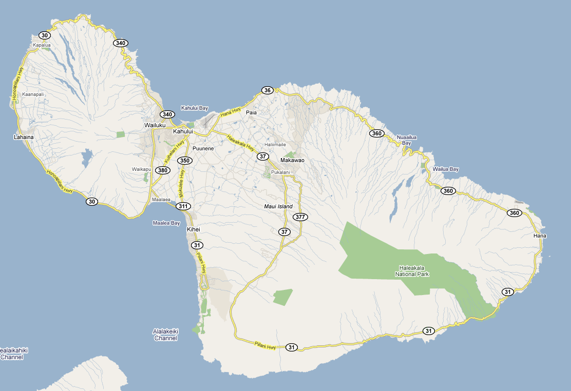